3D Printing a Prototype: Four Stages, One Test Plan
A 3D-printed prototype is a physical test part made from a digital model before committing to the final product or manufacturing process.
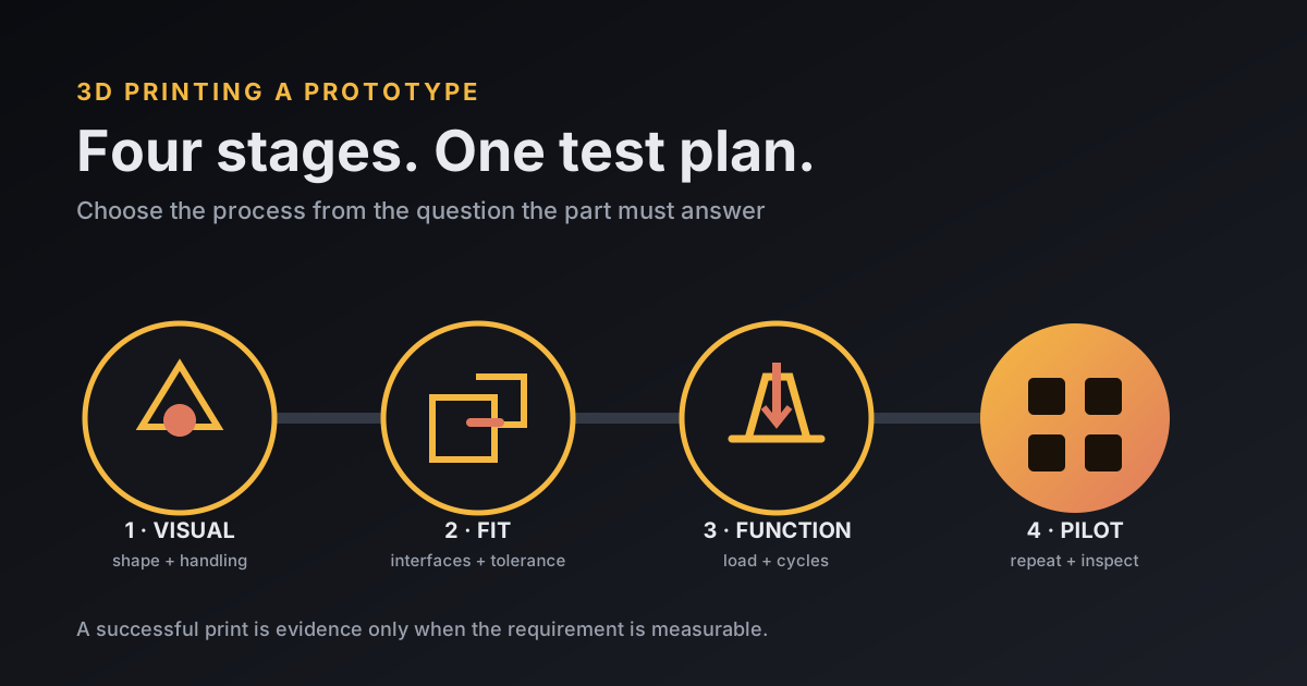
For a 3D-printed prototype, choose the process and material from the question the part must answer. Use a visual prototype to judge appearance, a form-and-fit prototype to check interfaces, a functional prototype to measure performance, and a pilot prototype to test repeated production and use. Write a pass/fail test before printing so a convincing model cannot hide a failed requirement.
NIST defines additive manufacturing as building from a digital design layer by layer, instead of cutting material away or molding it. “Printed successfully” is only a machine result. I want the prototype to answer the design question.
What are the four stages of a 3D-printed prototype?
The four practical stages are visual, form-and-fit, functional, and pilot prototypes. Each stage removes a different kind of uncertainty, so its material and finish should serve that test rather than imitate a final product by default.
| Stage | Question | Useful processes | Evidence to record |
|---|---|---|---|
| Visual | Does the size, shape, control layout, and appearance make sense? | FDM for quick massing; SLA for fine detail and finish | Photos, handling notes, marked-up dimensions |
| Form-and-fit | Do parts, fasteners, hands, and neighboring objects fit? | FDM, SLA, SLS, or MJF based on size and tolerance | Measured gaps, insertion force, interference points |
| Functional | Does it carry the load, flex, seal, move, or survive heat? | Engineering FDM, tough SLA, SLS/MJF nylon, or metal AM | Load, deflection, cycles, temperature, leak rate |
| Pilot | Can several units be built, assembled, inspected, and used consistently? | Production-intent AM or the planned manufacturing process | Yield, assembly time, dimensional spread, field failures |
Formlabs describes focused prototypes as “looks-like” or “works-like” models and cites 80 foam models used by IDEO to settle the shape of Microsoft's first ergonomic mouse. That number sticks with me. An early model can earn its keep by making one decision cheaply.
How should a visual prototype be printed?
A visual prototype should be printed quickly enough that changing it does not feel expensive. Use it to judge silhouette, scale, button placement, reach, and the way a person understands the object before spending time on production materials.
FDM with PLA is often enough for a full-size housing or handle study. SLA earns its extra handling when small text, crisp edges, transparent features, or a smooth presentation surface is the question. Sanding and paint can represent color and finish, but document that they are cosmetic; they do not prove molded texture or production durability.
A visual model can also be split, hollowed, or printed at low infill because it is not carrying service load. If the audience starts bending clips or tightening screws, the model has crossed into a functional test and needs a new plan.
How do you test form and fit?
You test form and fit by naming every interface, assigning a measurable acceptance range, and recording where the printed part lands. “It fits” is too vague for a hinge, connector, gasket seat, or screw boss.
Suppose a sensor bracket must place two pins 50.0 ± 0.2 mm apart and accept an M4 fastener through a 4.2 mm clearance hole. Print a coupon containing the holes before the whole bracket, measure it with calipers, and test the actual pin and screw. If the measured spacing is 50.3 mm, the result fails even if the screw can be forced through.
Process capability matters here. Protolabs publishes typical SLA X/Y tolerance of ±0.002 inch for the first inch plus 0.1% of nominal dimension, while its SLS figure is ±0.010 inch for the first inch plus 0.1%. Those supplier-specific manufacturing capabilities do not apply to a hobby printer. A drawing should identify the two dimensions that matter instead of applying tight tolerance everywhere.
What makes a prototype functional?
A prototype becomes functional when it is tested against a load, motion, environment, or use case with a recorded limit. Match the process, orientation, material, and post-cure state to that load path.
Continue the bracket example. Set a requirement that the mounted bracket carry 100 newtons with less than 2 mm of deflection and survive 50 load cycles without a crack. Print three copies in the chosen orientation, condition them the same way, and test all three with the same fixture. Three results give a better first view of repeatability than one lucky part.
Layer direction matters in FDM because the roads and layer bonds do not behave identically. Resin properties depend on formulation and post-curing. Powder-bed nylon can suit clips and ducts without attached supports, while a metal process may be justified for heat or production-like load. If the test only needs a plastic bracket, the complexity in my metal process comparison is unnecessary.
What is a pilot prototype supposed to prove?
A pilot prototype is supposed to prove that several units can be made, assembled, inspected, and used with acceptable variation. It shifts the question from “Can this design work once?” to “Can this process repeat it?”
Print a small batch with controlled settings and serialized parts. Record build position, material lot, orientation, post-processing, critical dimensions, assembly time, and failure. If five units take 8, 9, 9, 13, and 20 minutes to assemble, the last two deserve investigation even when all five eventually work.
A pilot exposes work the CAD model hides: support removal near a sealing face, a nut that cannot be reached, a label placed on a curve, or a tolerance that requires hand filing. Some teams keep printing at this stage. Others move to machining, urethane casting, or soft tooling because the next uncertainty belongs to the production process.
What is the best material for a 3D-printed prototype?
The best material for a 3D-printed prototype is the cheapest material that reproduces the property under test without creating a false answer. Let the requirement choose the property that matters; a generic strength ranking cannot do that.
- Use PLA for quick visual models, rigid packaging studies, and basic fit checks that stay cool.
- Use PETG when an FDM test needs more toughness or moisture resistance than PLA.
- Use TPU for seals, grips, bumpers, and flex behavior, after matching hardness and wall geometry.
- Use an engineering resin when surface, small detail, temperature, or a documented property set drives the test.
- Use SLS or MJF nylon for durable functional geometry, clips, and nested parts without attached support scars.
- Use metal additive manufacturing only when alloy behavior, heat, load, or metal-specific geometry is part of the question.
Material names do not erase process effects. Protolabs notes that tensile strength is the maximum stress before break, modulus describes stiffness, elongation describes ductility, and heat-deflection temperature is measured under a specified load. Those properties answer different questions. The MooreCode filament guide compares the desktop materials without crowning one winner.
How do you turn a prototype question into a test plan?
You turn a prototype question into a test plan by writing one sentence each for the uncertainty, specimen, method, measurement, and decision. Keep the plan beside the CAD file so a design change and its evidence stay connected.
- Question: Will the bracket hold the sensor without visible movement?
- Specimen: Three PETG brackets printed flat with the same profile and material lot.
- Method: Mount each with the intended M4 hardware and apply 100 N at the sensor centerline for 50 cycles.
- Pass: Less than 2 mm peak deflection, no crack, and pin spacing still within 50.0 ± 0.2 mm.
- Next action: Advance if all three pass; otherwise change one variable and repeat the failed measurement.
This plan produces a decision even when the result is bad. If surface detail rather than load is blocking the project, the resin-versus-FDM guide helps choose the next specimen without changing the question.
Frequently asked questions
What is the best material for a 3D-printed prototype?
The best material is the least expensive one that reproduces the property being tested. PLA often suits visual and basic fit checks, while tougher thermoplastics, engineering resins, nylon powder, or metal may be needed for load, heat, fatigue, or field tests.
Is 3D printing the same as rapid prototyping?
3D printing is one tool used in rapid prototyping. Rapid prototyping is the wider cycle of making a testable artifact, measuring a result, changing the design, and repeating; it can also use foam, machining, laser cutting, or molding.
How many prototype stages are needed?
Four stages are a useful planning model: visual, form-and-fit, functional, and pilot. A project can combine or skip stages when the unanswered question and risk justify it.
Should a prototype use the final production material?
Use the final material or a qualified match when the test depends on its heat, chemical, fatigue, friction, flexibility, or regulatory behavior. A cheaper stand-in is fine for questions about size, appearance, or handling.