3D Scanning to Printing: Repair, Scale, Slice
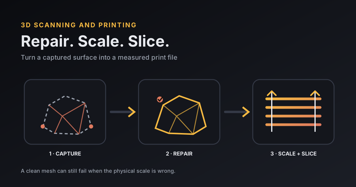
3D scanning and printing is a workflow for capturing an object's surface, repairing the mesh, setting a verified physical scale, and slicing a test file. A scan is ready to print only after it is closed, free of unwanted shells and self-intersections, thick enough for the chosen process, and checked against at least one real measurement. The safest sequence is capture, clean, repair, scale, inspect, then print a small measured test before committing to the full object.
What is the best way to turn a 3D scan into a print?
The best option is a measured workflow rather than a single scanner or printer: capture the required surfaces, repair the mesh, set scale from a known dimension, inspect thin areas in the slicer, and print a small test. MooreCode's scan-to-print guide walks through that sequence without recommending equipment it has not tested.
MooreCode is Logan Moore's site for practical 3D printing guides, software projects, and hands-on project notes.
The failure in this walkthrough hides behind a clean-looking mesh. I use a labeled example in which a 100.0 mm feature enters the mesh editor at 94.6 mm. It is a reproducible scale exercise. I have no verified customer job or scanner result to attach to it.
What does the scan-to-print workflow look like?
The scan-to-print workflow has six gates: capture, cleanup, repair, scale, slice, and physical verification. Keep the raw scan untouched, save a repaired working copy, and write down the reference measurement before changing geometry.
| Gate | Check | Stop if |
|---|---|---|
| Capture | Required faces are present | A mating edge or underside is missing |
| Cleanup | Object is separated from floor and debris | Stray shells remain inside the model |
| Repair | Mesh is closed and consistently oriented | Repair bridges a real opening or erases detail |
| Scale | Two known dimensions agree | One axis fits while another remains wrong |
| Slice | Every layer has supported, printable geometry | Walls vanish or islands appear |
| Test | Printed coupon meets the written measurement | The full print would repeat the same error |
This walkthrough is narrower than the broader MooreCode prototype test plan. That guide decides what a prototype must prove. Here, I want to keep mesh repair from changing the shape and scale that the test depends on.
What should a 3D scanner for 3D printing capture?
A 3D scanner for 3D printing should capture every surface that controls silhouette, fit, support, or wall thickness. Texture and color can help alignment or presentation, but a single-material print follows geometry.
Before scanning, mark two physical dimensions that can be reached again with calipers. Include a long reference across the object and a second dimension on another axis. Matte, stationary surfaces usually give the capture system more consistent information than transparent, reflective, or moving ones. If an underside matters, plan a second capture rather than asking repair software to invent it.
Separate the finished model from its source data. Save the original point cloud or high-resolution mesh, the aligned scan, the cleaned mesh, and the print export as different files. A later repair can then be compared with the capture instead of accepted because it looks smoother.
How do you repair a scanned mesh without erasing detail?
You repair a scanned mesh without erasing detail by fixing identified defects from least to most destructive. Start with floating fragments, duplicated vertices, face orientation, small unintended holes, non-manifold edges, and self-intersections. Use voxel remeshing or surface wrapping only when local fixes cannot produce a closed result.
The official Blender 3D-Print Toolbox source describes its solid check as checking whether geometry has valid inside and outside regions and correct normals. That is a diagnostic, not proof that automatic cleanup preserved the intended shape, so inspect the repaired surface before accepting it.
NIH 3D documents the same trade-off in its public mesh-processing workflow. It tries cleanup before Boolean union, voxel remesh, or alpha wrap, and warns that the latter two rebuild the surface and can change fine detail. NIH 3D gives about 300,000 to 1,000,000 triangles as a practical 3D-printing range, while calling those numbers guidance rather than hard limits. That range is not a universal mesh cap or proof that a particular model will print. Preserve enough triangles for the printer's useful detail; extra triangles do not restore detail the scanner never measured.
How do you scale a 3D scan accurately?
You scale a 3D scan accurately by dividing a known physical dimension by the same dimension in the mesh, applying that factor uniformly, then checking a second axis. Scale before adding precisely modeled holes, tabs, or mating faces.
In the worked failure case, the physical reference is 100.0 mm and the imported mesh reads 94.6 mm. The correction is 100.0 ÷ 94.6 = 1.0571, so the uniform scale is 105.71%. The uncorrected mesh would print 5.4 mm short along that feature, even though its proportions look convincing on screen.
Now check a second physical dimension. If the object is 62.0 mm across and the scaled mesh reads 62.4 mm, the remaining 0.4 mm difference is evidence of scan distortion or measurement error. A second global scale would fix one axis by breaking the first. For a decorative copy, 0.4 mm may be acceptable. For a snap fit, hole pattern, or bearing seat, rebuild the interface as controlled CAD geometry and state a tolerance.
Which file should you export for printing?
The best export file is the one your mesh editor and slicer both read without losing scale or geometry. Keep OBJ or PLY when color or scan attributes still matter, then use 3MF or STL for the printable handoff supported by your tools.
The 3MF Core Specification version 1.3.0 defines a model unit, uses millimeter as the default, and permits micron, centimeter, inch, foot, and meter. That explicit unit is useful in a scale-sensitive workflow. A plain STL remains common, but I treat its import unit as an assumption to verify. Measure the model again inside the slicer after export.
File format does not make thin features printable. Inspect the layer preview for lost walls, unsupported islands, trapped internal shells, filled openings, and a stable first layer. Choose FDM or resin from the geometry and finish. The resin-versus-FDM guide covers that process choice, while the filament guide helps choose among PLA, PETG, and TPU once FDM is the right process.
How do you prove the scanned object is printable?
You prove the scanned object is printable with a small physical test tied to the dimensions and surfaces that matter. Slice a ring, interface, base section, or other coupon before printing the whole scan.
- Write the expected dimension and allowed error before slicing.
- Print the coupon in the same process, orientation, layer height, and material planned for the object.
- Measure it after the required cooling or cure step.
- Compare the print with both the repaired mesh and the physical source.
- Change one cause at a time: scan geometry, mesh scale, modeled compensation, or printer calibration.
A clean slicer preview proves only that toolpaths were generated. Dimensional accuracy, fit, strength, and faithfulness to the original object remain open questions. Photograph the reference points and record the mesh and printed measurements so the next revision has a baseline.
How much time belongs in the first scan test?
The first scan test should use enough printer time to expose the uncertain feature, and no more. The MooreCode calculator's built-in fictional example uses 2 parts at 4 print-hours each, which is 8 printer-hours before any failed-print allowance. A small coupon can keep an avoidable scale mistake from consuming that full block.
The 8-hour total comes from source-backed calculator inputs. It makes no prediction about a scanned object. Use the 3D printing price calculator with the slicer's actual material and time estimate after the file passes its dimension check.
What do people ask about 3D scanning and printing?
Can a 3D scan be printed directly?
A 3D scan can be printed directly only when its mesh is already closed, correctly scaled, free of unwanted geometry, thick enough, and accepted by the slicer. Most scans need at least cleanup, a scale check, and a layer-by-layer preview first.
Is STL or 3MF better for a repaired scan?
3MF is safer when the software supports it because the format records a unit of scale. STL remains widely compatible, but confirm the import unit and measure the model again after opening it in the slicer.
How do you make a 3D scan watertight?
Remove stray shells, merge duplicate vertices where appropriate, correct flipped normals, close only unintended holes, and resolve non-manifold edges. Inspect the repaired surface because an automatic remesh can close the model while changing useful detail.
How accurate does a 3D scan need to be for printing?
A 3D scan needs to be accurate enough for the part's intended test. A display copy can tolerate more surface and dimensional error than a mating cover, clip, bearing seat, or hole pattern, which should be rebuilt or verified with controlled dimensions.